


|
Sine Wave BLDC E-Bike Controller 350/450/500/600/800/1000W, 48/64/84V, 3-Mode Item NO.: 10704791


Copy and share this link on social network or send it to your friends
Copy| Product Name | Sine Wave BLDC E-Bike Controller 350/450/500/600/800/1000W, 48/64/84V, 3-Mode |
| Item NO. | 10704791 |
| Weight | 1 kg = 2.2046 lb = 35.2740 oz |
| Category | 35910 |
| Creation Time | 2025-12-23 |
Product Specifications:
• Rated Power: 350W
• Operating Voltage: 1.1±4.2V (Please verify this specification, as it is atypical for e-bike controllers. Common voltages are 36V, 48V, etc.)
• Rated Current: 17A
• Waterproof Rating: Splash-proof
• Brake Signal Type: High/Low Level
• Product Dimensions: 10.5cm (L) x 6.5cm (W)
• Product Functions: 3-Speed, Anti-Theft, Cruise Control, E-ABS (Electronic Brake)
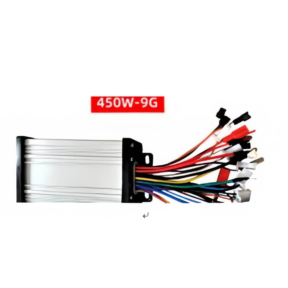
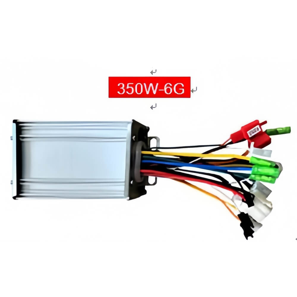
• Rated Power: 450W
• Operating Voltage: 48V / 60V / 64V (Compatible)
• Rated Current: 23A±1A
• Waterproof Rating: Splash-proof
• Brake Signal Type: High/Low Level Brake
• Product Dimensions: 13cm (L) x 8.7cm (W)
• Product Functions: 3-Speed, Anti-Theft Alarm, Cruise Control
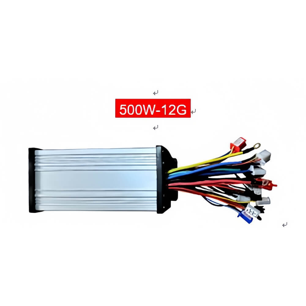
• Rated Power: 500W
• Operating Voltage: 48V / 60V / 64V / 72V (Compatible)
• Rated Current: 30A±2A
• Waterproof Rating: Splash-proof
• Brake Signal Type: High/Low Level Brake
• Product Dimensions: 15cm (L) x 8.7cm (W)
• Product Functions: 3-Speed, Anti-Theft Alarm, Cruise Control
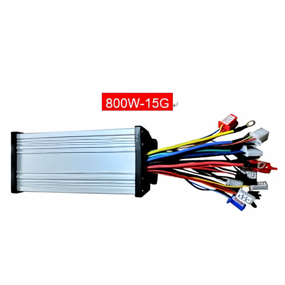
• Rated Power: 800W
• Operating Voltage: 48V / 60V / 64V / 72V (Compatible)
• Rated Current: 34A±2A
• Waterproof Rating: Splash-proof
• Brake Signal Type: High/Low Level Brake
• Product Dimensions: 18.5cm (L) x 8.7cm (W)
• Product Functions: 3-Speed, Anti-Theft Alarm, Cruise Control
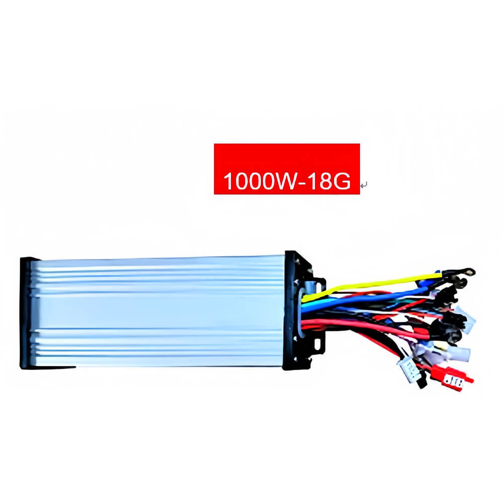
• Rated Power: 1000W
• Operating Voltage: 48V / 60V / 64V / 72V (Compatible)
• Rated Current: 42A±2A
• Waterproof Rating: Splash-proof
• Brake Signal Type: High/Low Level Brake
• Product Dimensions: 21.5cm (L) x 9.2cm (W)
• Product Functions: 3-Speed, Anti-Theft Alarm, Cruise Control
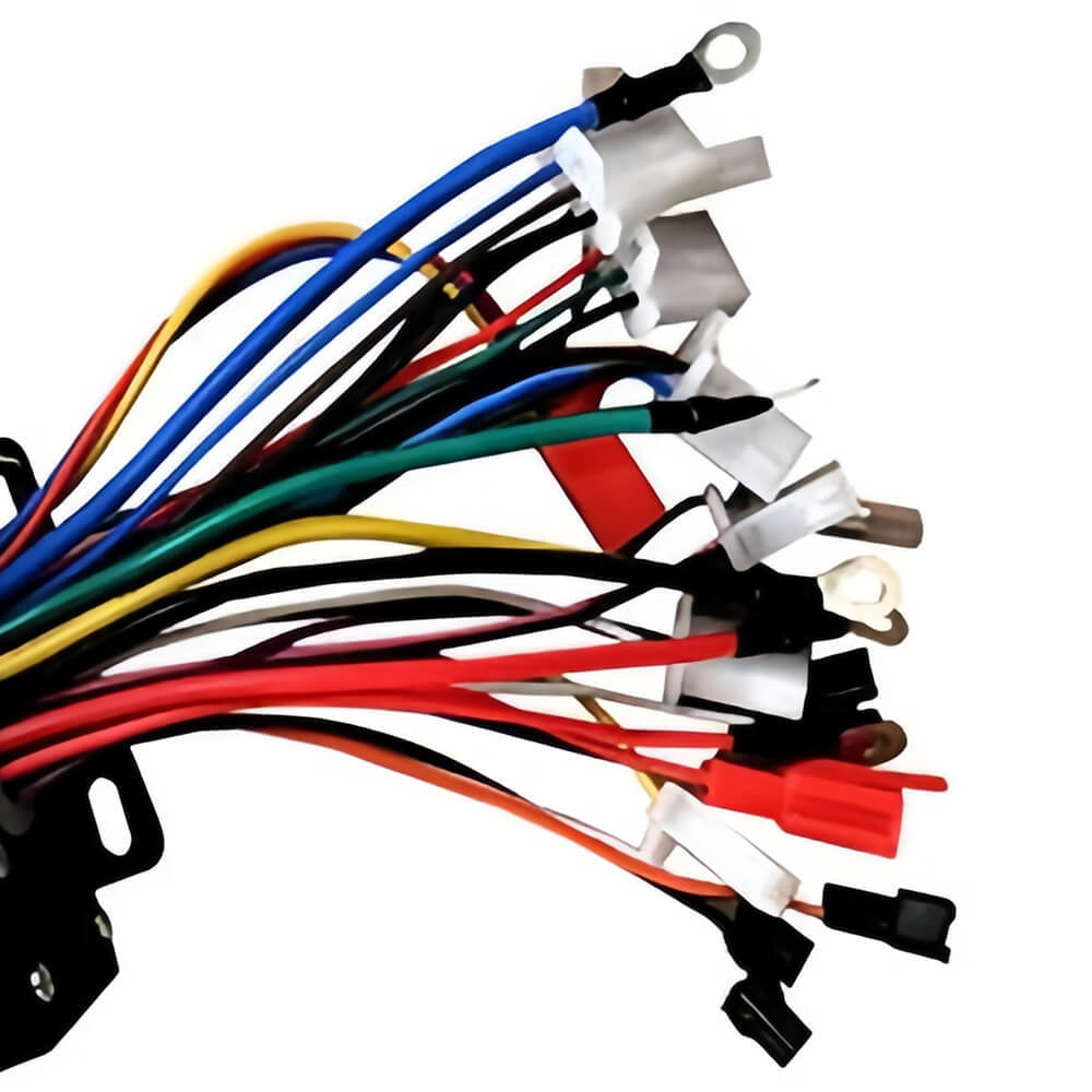
Professional E-Bike Controller Installation Guide - Universal & Easy to Connect This detailed 10-step guide ensures a correct and safe installation of your new brushless controller. Please follow the steps carefully for optimal performance. STEP 1: Connect the Motor Wires (3 Phases) 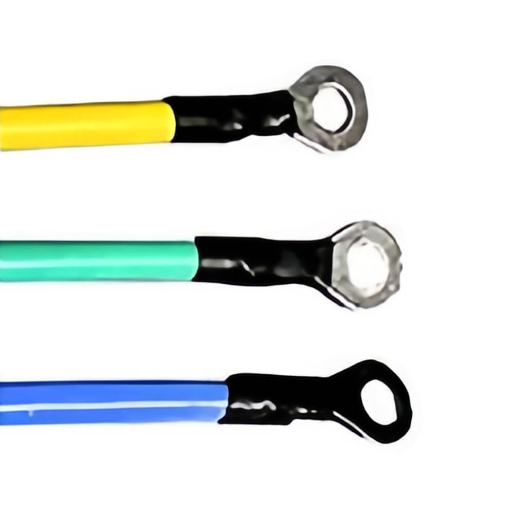
• Connect the three thick motor wires from the controller (Yellow, Green, Blue) to the corresponding three wires from your e-bike motor. The order does not matter initially.
• Test: After connecting, gently try to rotate the rear wheel by hand. It should spin freely without resistance.
•
o No Resistance: Proceed to Step 2.
§ Resistance Found: Check the connections. Ensure wires are not touching each other or the frame.
• Motor Health Check Tip:Briefly touch the three motor wires from the bike together in pairs. If the wheel becomes hard to turn, the motor is good. If no resistance is felt, the motor may have an issue.
STEP 2: Connect Power & Ignition Wires
• Identify the controller's thick Red wire (Battery Positive +) and thick Black wire (Battery Negative -). 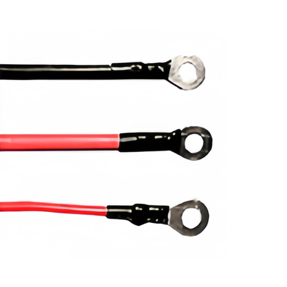
• Connect them to your e-bike's corresponding battery positive and negative wires.
• CRUCIAL: Ensure polarity is correct. Reversing positive and negative will instantly damage the controller.
• Locate the thin Red wire (Ignition Switch Wire). Connect it to your e-bike's ignition switch wire.
•
o If your bike has no ignition wire, simply connect this thin red controller wire to the battery positive wire.
STEP 3: Self-Learning Function (Set Rotation Direction)
• Locate the pair of white wires (Self-Learning Wires). Plug them together.
• Turn on the e-bike's ignition/key.
• The motor should start spinning automatically.
• 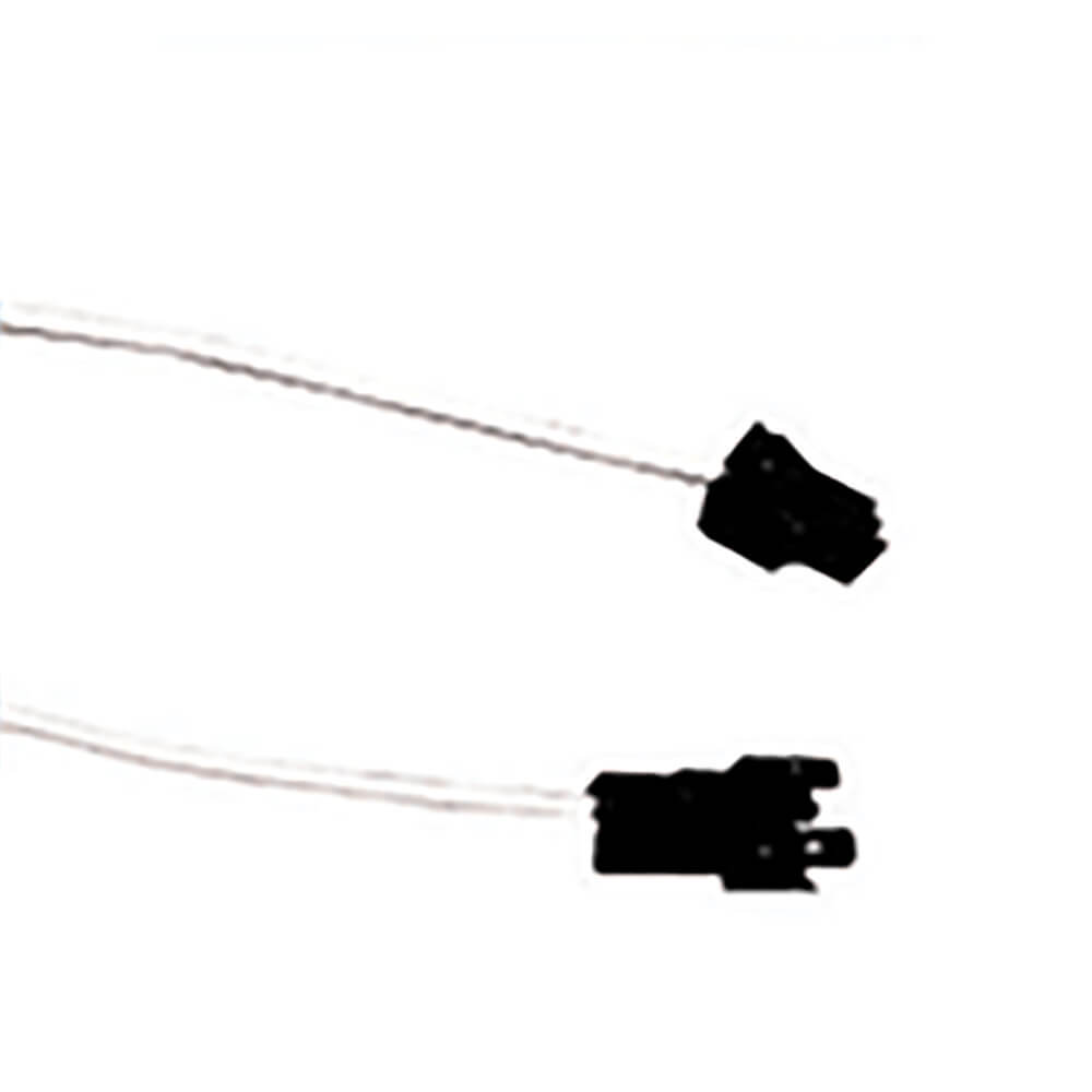
o Spins Forward: Unplug the self-learning wires. Setup is complete.
§ Spins Backward (Reverse): Unplug the self-learning wires while the motor is spinning, then plug them back together. The motor direction should switch to forward. Then unplug the wires permanently.
• This step confirms the controller is functioning correctly. If the motor does not spin, the controller may be faulty.
STEP 4: Connect Hall Sensor Wires (Optional but Recommended)
• Find the 5-pin connector (Hall Sensor Wires). Align and plug it into the bike's corresponding connector. 
• Note: The controller's Red wire is positive (+) and Black wire is negative (-). As long as these are correct, the other three wire colors can vary.
• This controller is sensorless and can run without Hall sensors. However, if your motor's Hall sensors are faulty, you may experience:
o Jerky startup or lack of power from a stop (runs smoothly once moving).
o Loss of anti-theft wheel lock feature (alarm may still work).
o Loss of high-speed mode (low speed may still work).
STEP 5: Connect Throttle Wires
• Locate the controller's throttle wires: Red (Positive +), Black (Negative -), Green (Signal).
• Connect them to your e-bike's throttle handle wires (consult throttle handle wiring if unsure). 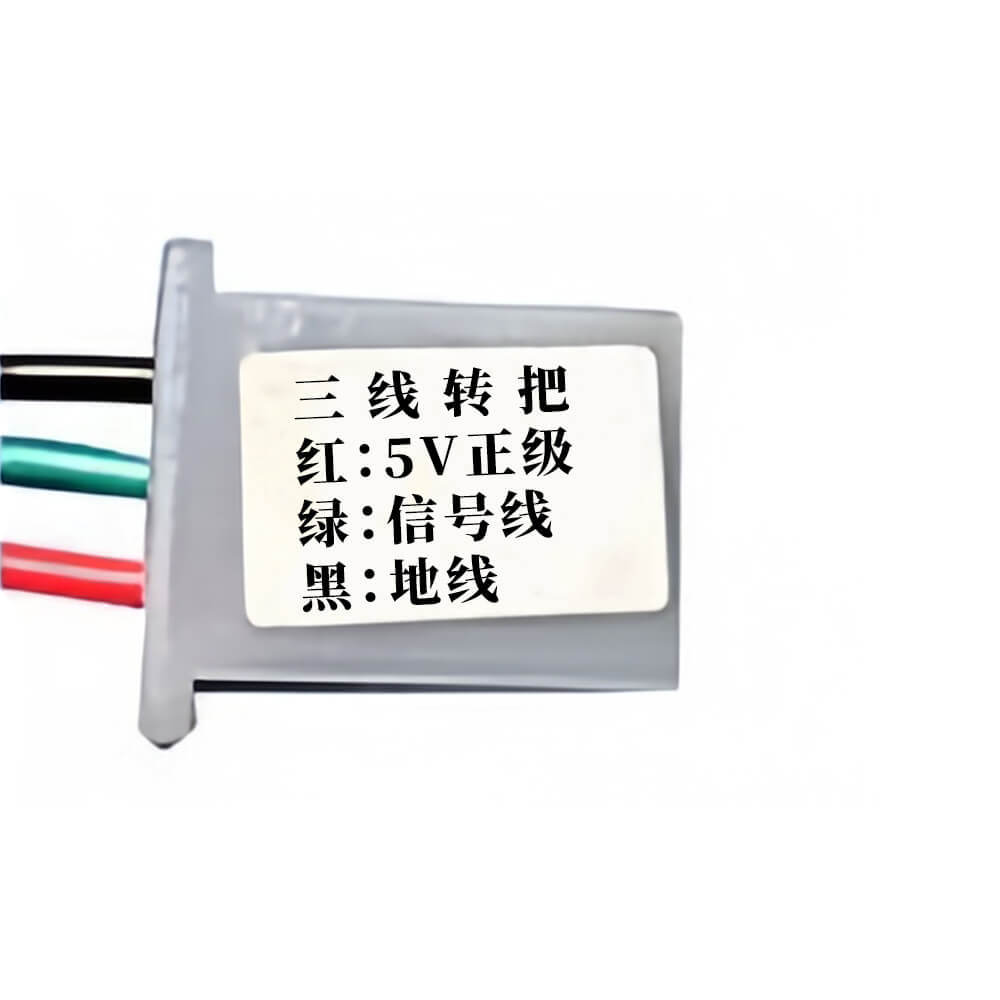
• Turn the throttle. The motor should respond.
•
o No Response? Check:
1. Throttle wire polarity (Red+/Black-) is correct.
2. The throttle itself may be faulty (a common replacement part).
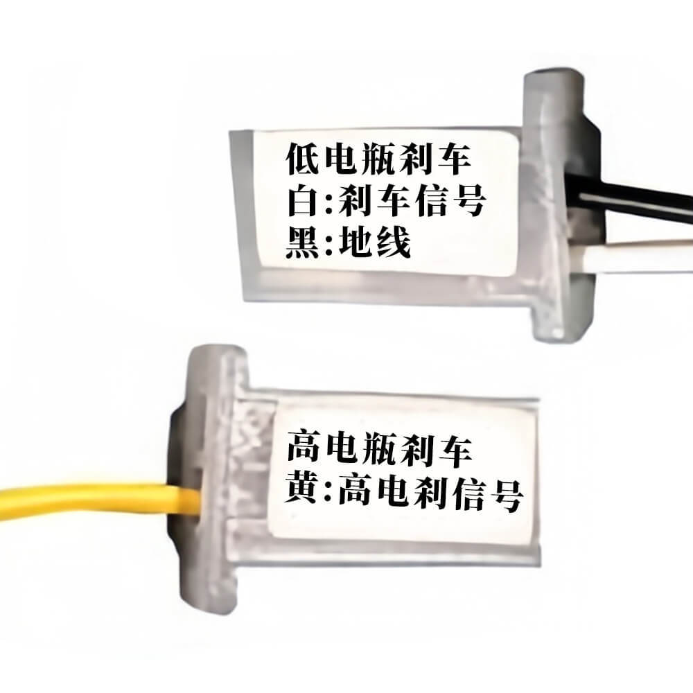
STEP 6: Connect Brake Cut-off Wires (High/Low Level)
• The controller supports both brake types:
o High-Level Brake: A single Yellow wire. Use if your brake lever has one wire.
o Low-Level Brake: A White & Black wire pair. Use if your brake lever has two wires.
• Connecting either will activate the brake cut-off function (cuts power to motor when braking).
• 
o For combined throttle/brake units:Connect the Low-Level brake wires parallel to the throttle wires for brake cut-off.
• E-ABS (Electronic Braking): This feature is automatic. When you brake, the motor generates a reverse force, providing gentle braking. A occasional "clicking" sound is normal and not harmful to the motor.
STEP 7: Connect Instrument/Gauge Wire
• A single thin Green wire is provided for the speedometer.
• Best for analog/pointer gauges. Compatibility with digital/LCD displays is not guaranteed and may vary. 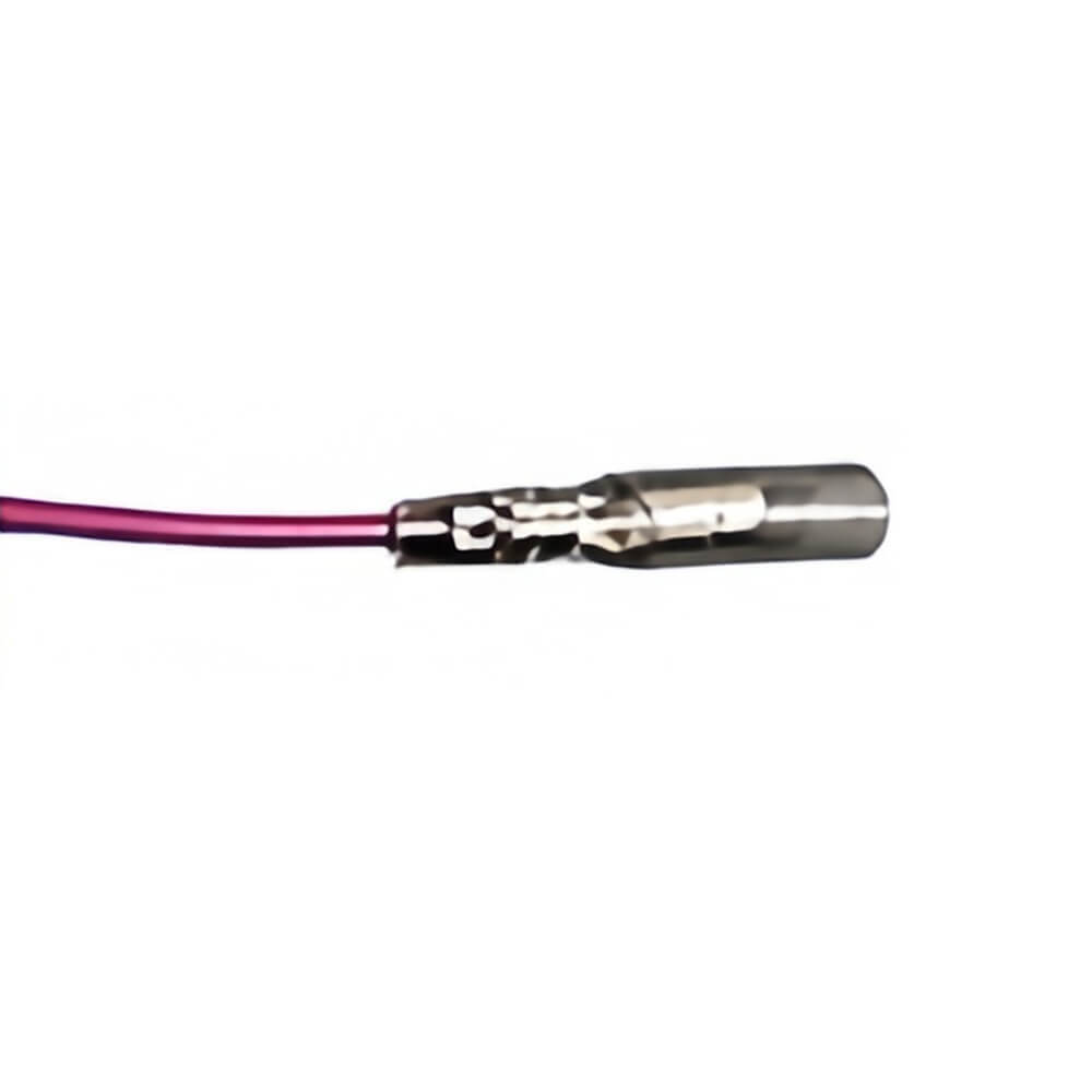
STEP 8: Connect Cruise Control Wire
• Enables cruise control function.
• 
o Auto Cruise: Simply connect (short) the cruise control wires together.
§ Button Cruise: Connect a separate cruise control button switch to these wires.
STEP 9: Connect Anti-Theft Alarm Wires (If Applicable)
• This is for activating the alarm function. The connector has two groups:
o Alarm Power: Red (+), Black (-) – Connect to battery.
o Alarm Signals: Red (Ignition), Yellow (Wheel Sensor), Blue (Arm/Disarm Signal).
• Caution: Do not mix these wires up. Connect strictly according to their labels.
STEP 10: Connect Reverse Function Wire
• This function creates a closed circuit for reverse operation. Connect only if you need this feature.
• Important Note: 350W controllers do NOT have a reverse function. Please confirm your controller model.
Safety Disclaimer: Installation requires technical skill. Ensure all connections are secure and insulated. We are not liable for incorrect installation, damage, or injury. Please double-check your bike's wiring diagram.
Notice:
If you are not a professional or are unsure which model is compatible with your e-bike, simply take clear, complete photos of your original controller. We will gladly recommend the correct matching product for you.
You May Also Like


Recently Viewed


- Company Info
- Feedback
- Customer Reviews
- About Us
- Contact Us
- News
- Privacy Policy
- User Center
- Forget Password
- My Orders
- Tracking Order
- My Account
- Wanting to cooperate with us?
- Register
- Not Satisfied with our products or service?
- Payment & Shipping
- Customs & Taxes
- Locations We Ship To
- Shipping Methods
- Payment Methods
- Newsletter


 Leave a message
No related record found